Worm gears are usually used when large quickness reductions are needed. The decrease ratio is determined by the number of begins of the worm and number of the teeth on the worm equipment. But worm gears possess sliding get in touch with which is tranquil but will produce heat and have relatively low tranny efficiency.
As for the materials for creation, in general, worm is made from hard metal as the worm gear is produced out of relatively soft steel such as for example aluminum bronze. This is since the number of teeth on the worm gear is relatively high in comparison to worm using its number of starts being generally 1 to 4, by reducing the worm equipment hardness, the friction on the worm teeth is reduced. Another characteristic of worm manufacturing may be the need of specific machine for gear slicing and tooth grinding of worms. The worm gear, however, may be made with the hobbing machine utilized for spur gears. But due to the  different tooth shape, it isn’t possible to cut a number of gears simultaneously by stacking the gear blanks as can be carried out with spur gears.
The applications for worm gears include equipment boxes, angling pole reels, guitar string tuning pegs, and where a delicate speed adjustment by utilizing a big speed reduction is necessary. While you can rotate the worm gear by worm, it is generally extremely hard to rotate worm utilizing the worm gear. That is called the self locking feature. The self locking feature cannot always be assured and another method is preferred for accurate positive reverse prevention.
Also there exists duplex worm gear type. When working with these, you’ll be able to change backlash, as when one’s teeth put on necessitates backlash adjustment, without requiring a alter in the center distance. There are not too many manufacturers who can produce this kind of worm.
The worm equipment is additionally called worm wheel in China.
A worm equipment is a gear comprising a shaft with a spiral thread that engages with and drives a toothed wheel. Worm gears are a vintage style of gear, and a version of one of the six simple machines. Essentially, a worm equipment can be a screw butted up against what appears like a standard spur gear with slightly angled and curved the teeth.
It changes the rotational movement by 90 degrees, and the plane of motion also changes because of the position of the worm upon the worm wheel (or just “the wheel”). They are typically comprised of a metal worm and a brass wheel.
Worm Gear
Figure 1. Worm equipment. Most worms (but not all) are at underneath.
How Worm Gears Work
An electric motor or engine applies rotational power via to the worm. The worm rotates against the wheel, and the screw encounter pushes on one’s teeth of the wheel. The wheel is definitely pushed against the strain.
Worm Gear Uses
There are a few reasons why one would choose a worm gear over a standard gear.
The first one may be the high reduction ratio. A worm gear can have an enormous reduction ratio with small effort – all one must do can be add circumference to the wheel. Thus you can use it to either significantly increase torque or greatly reduce speed. It’ll typically take multiple reductions of a typical gearset to attain the same reduction degree of a single worm gear – which means users of worm gears have got fewer shifting parts and fewer areas for failure.
A second reason to use a worm gear is the inability to reverse the direction of power. Because of the friction between your worm and the wheel, it really is virtually impossible for a wheel with pressure used to it to start the worm moving.
On a standard gear, the input and output can be turned independently once enough force is applied. This necessitates adding a backstop to a standard gearbox, further raising the complication of the gear set.
YOU WILL WANT TO to Use Worm Gears
There is one especially glaring reason why one would not choose a worm gear more than a standard gear: lubrication. The movement between your worm and the wheel equipment faces is entirely sliding. There is absolutely no rolling component to the tooth contact or conversation. This makes them fairly difficult to lubricate.
The lubricants required are often very high viscosity (ISO 320 and better) and thus are tough to filter, and the lubricants required are typically specialized in what they perform, requiring a product to be on-site specifically for that type of equipment.
Worm Gear Lubrication
The primary problem with a worm gear is how it transfers power. It is a boon and a curse simultaneously. The spiral movement allows large sums of decrease in a comparatively little bit of space for what’s required if a standard helical equipment were used.
This spiral motion also causes a remarkably problematic condition to be the principal mode of power transfer. That is commonly known as sliding friction or sliding wear.
New call-to-action
With an average gear set the energy is transferred at the peak load stage on the tooth (referred to as the apex or pitchline), at least in a rolling wear condition. Sliding occurs on either side of the apex, however the velocity is fairly low.
With a worm gear, sliding motion may be the only transfer of power. As the worm slides over the tooth of the wheel, it slowly rubs off the lubricant film, until there is absolutely no lubricant film left, and as a result, the worm rubs at the metallic of the wheel in a boundary lubrication regime. When the worm surface area leaves the wheel surface, it picks up more lubricant, and begins the process over again on another revolution.
The rolling friction on a typical gear tooth requires small in the way of lubricant film to fill in the spaces and separate both components. Because sliding happens on either part of the apparatus tooth apex, a somewhat higher viscosity of lubricant than is definitely strictly necessary for rolling wear must overcome that load. The sliding happens at a comparatively low velocity.
The worm on a worm set gear turns, and while turning, it crushes against the load that’s imposed on the wheel. The only way to prevent the worm from touching the wheel can be to have a film thickness huge enough to not have the whole tooth surface area wiped off before that area of the worm has gone out of the load zone.
This scenario takes a special sort of lubricant. Not only will it should be a relatively high viscosity lubricant (and the higher the load or temperature, the higher the viscosity should be), it will need to have some way to help overcome the sliding condition present.
Read The Right Way to Lubricate Worm Gears for more information on this topic.
Viscosity is the major aspect in preventing the worm from touching the wheel in a worm equipment set. As the load and size of gearing determines the required lubricant, an ISO 460 or ISO 680 is rather common, and an ISO 1000 is not unheard of. If you have ever really tried to filter this selection of viscosity, you understand it is problematic since it is probably that none of the filters or pumps you possess on-site will be the correct size or rating to function properly.
Therefore, you’ll likely have to get a particular pump and filter for this kind of unit. A lubricant that viscous requires a slower operating pump to prevent the lubricant from activating the filter bypass. It will also require a huge surface area filter to permit the lubricant to flow through.
Lubricant Types to consider
One lubricant type commonly used with worm gears is mineral-based, compounded gear oils. There are no additives that can be placed into a lubricant that may make it conquer sliding wear indefinitely, but the organic or synthetic fatty additive combination in compounded equipment oils results in great lubricity, providing an extra way of measuring protection from metal-to-metal get in touch with.
Another lubricant type commonly used in mixture with worm gears is mineral-based, industrial extreme pressure (EP) equipment oils. There are several problems with this kind of lubricant if you are using a worm gear with a yellow metallic (brass) component. However, should you have relatively low operating temps or no yellow metallic present on the apparatus tooth areas, this lubricant is effective.
Polyalphaolefin (PAO) gear lubricants work well in worm equipment applications because they naturally have got great lubricity properties. With a PAO gear oil, it’s important to view the additive package, because these can possess EP additives. A standard-duty antiwear (AW) fortified gear essential oil will typically become acceptable, but be sure the properties are compatible with most metals.
The author recommends to closely watch the wear metals in oil evaluation testing to ensure that the AW bundle isn’t so reactive concerning trigger significant leaching from the brass. The result should be far less than what would be seen with EP even in a worst-case scenario for AW reactivity, nonetheless it can arrive in metals screening. If you want a lubricant that can manage higher- or lower-than-typical temperature ranges, a suitable PAO-based product is likely available.
Polyalkylene glycols (PAG), a fourth kind of lubricant, are getting more common. These lubricants have exceptional lubricity properties, , nor contain the waxes that trigger low-temperature issues with many mineral lubricants, making them a great low-temperature choice. Caution must be taken when working with PAG oils because they’re not compatible with mineral oils, plus some seals and paints.
Metallurgy of Worm Gears
The most common worm gears are made with a brass wheel and a steel worm. This is because the brass wheel is normally easier to replace than the worm itself. The wheel is manufactured out of brass since it is designed to be sacrificial.
When the two surfaces come into contact, the worm is marginally safe from wear since the wheel is softer, and therefore, the majority of the wear occurs on the wheel. Oil analysis reports on this kind of unit more often than not show some degree of copper and low levels of iron – consequently of the sacrificial wheel.
This brass wheel throws another problem in to the lubrication equation for worm gears. If a sulfur-phosphorous EP gear essential oil is placed into the sump of a worm gear with a brass wheel, and the temperature is definitely high enough, the EP additive will activate. In normal steel gears, this activation generates a thin level of oxidation on the surface that helps to protect the apparatus tooth from shock loads and other extreme mechanical conditions.
On the brass surface however, the activation of the EP additive results in significant corrosion from the sulfur. In a short amount of time, you can shed a substantial portion of the load surface area of the wheel and trigger major damage.
Other Materials
Some of the less common materials found in worm gear pieces include:
Steel worm and steel worm wheel – This software doesn’t have the EP problems of brass gearing, but there is no room for mistake built into a gearbox like this. Repairs on worm equipment sets with this mixture of metal are usually more costly and more time eating than with a brass/steel worm gear set. This is since the material transfer associated with failure makes both worm and the wheel unusable in the rebuild.
Brass worm and brass worm wheel – This software is most likely found in moderate to light load circumstances because the brass can only hold up to a lower amount of load. Lubricant selection on this metal combination is flexible because of the lighter load, but one must still consider the additive limitations regarding EP due to the yellow metal.
Plastic on metal, on plastic, and other similar combinations – This is typically within relatively light load applications, such as robotics and auto components. The lubricant selection depends upon the plastic used, because many plastic varieties react to the hydrocarbons in regular lubricant, and therefore will demand silicon-based or other non-reactive lubricants.
Although a worm gear will always have a few complications compared to a standard gear set, it can easily be an effective and reliable device. With a little attention to setup and lubricant selection, worm gears can offer reliable service as well as any other type of gear set.
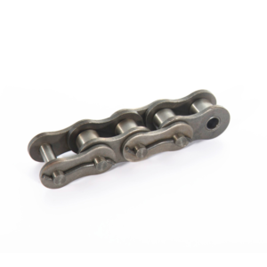
A worm drive is one simple worm gear set mechanism in which a worm meshes with a worm gear. Even it is simple, there are two important components: worm and worm equipment. (They are also called the worm and worm wheel) The worm and worm wheel is important motion control component providing large speed reductions. It can reduce the rotational acceleration or increase the torque output. The worm drive movement advantage is they can transfer motion in right angle. In addition, it comes with an interesting house: the worm or worm shaft can certainly turn the gear, but the gear can not really turn the worm. This worm drive self-locking feature let the worm gear has a brake function in conveyor systems or lifting systems.
An Introduction to Worm Gearbox
The most important applications of worm gears is utilized in worm gear box. A worm gearbox is called a worm decrease gearbox, worm gear reducer or a worm drive gearbox. It contains worm gears, shafts, bearings, and box frames.
The worm equipment, shafts, bearings load are supported by the container shell. Therefore, the gearbox housing must have sufficient hardness. Otherwise, it’ll result in lower transmitting quality. As the worm gearbox includes a durable, tranny ratio, little size, self-locking ability, and simple framework, it is often used across an array of industries: Rotary desk or turntable, material dosing systems, car feed machinery, stacking machine, belt conveyors, farm selecting lorries and more automation market.
How to Select High Efficient Worm Gearbox?
The worm gear manufacturing process is also not at all hard. However, there is a low transmission efficiency problem if you don’t understand the how to select the worm gearbox. 3 basic point to choose high worm gear efficiency that you need to know:
1) Helix angle. The worm gear drive efficiency mostly rely on the helix angle of the worm. Generally, multiple thread worms and gears can be more efficient than solitary thread worms. Proper thread worms can increase effectiveness.
2) Lubrication. To select a brand lubricating essential oil is an essential factor to boost worm gearbox performance. As the correct lubrication can decrease worm gear action friction and heat.
3) Materials selection and Gear Production Technology. For worm shaft, the material should be hardened steel. The worm gear material should be aluminium bronze. By reducing the worm gear hardness, the friction on the worm teeth is decreased. In worm production, to use the specialized machine for gear trimming and tooth grinding of worms can also increase worm gearbox effectiveness.
From a large transmission gearbox capacity to a straight small worm gearbox load, you can choose one from a wide range of worm reducer that precisely fits your application requirements.
Worm Gear Box Assembly:
1) You can complete the set up in six different ways.
2) The installation must be solid and reliable.
3) Make sure to examine the connection between the electric motor and the worm gear reducer.
4) You must make use of flexible cables and wiring for a manual set up.
With the help of the most advanced science and drive technology, we’ve developed several unique “square package” designed from high-quality aluminium die casting with a lovely appearance. The modular worm gearbox style series: worm drive gearbox, parallel shaft gearbox, bevel helical gearbox, spiral bevel gearbox, coaxial gearbox, correct angle gearbox. An NMRV series gearbox is certainly a typical worm gearbox with a bronze worm gear and a worm. Our Helical gearbox products comprises of four universal series (R/S/K/F) and a step-less rate variation UDL series. Their structure and function act like an NMRV worm gearbox.
Worm gears are made of a worm and a equipment (sometimes known as a worm wheel), with non-parallel, non-intersecting shafts oriented 90 degrees to each other. The worm is certainly analogous to a screw with a V-type thread, and the apparatus can be analogous to a spur gear. The worm is normally the generating component, with the worm’s thread advancing one’s teeth of the gear.
Like a ball screw, the worm in a worm gear might have an individual start or multiple starts – and therefore there are multiple threads, or helicies, on the worm. For a single-start worm, each full convert (360 degrees) of the worm advances the gear by one tooth. Therefore a gear with 24 teeth will provide a gear reduced amount of 24:1. For a multi-start worm, the apparatus reduction equals the number of teeth on the apparatus, divided by the amount of begins on the worm. (This is not the same as most other types of gears, where in fact the gear reduction is usually a function of the diameters of the two components.)
The worm in a worm gear assembly can have one start (thread) or multiple starts.
Image credit: Kohara Gear Industry Company, Ltd.
The meshing of the worm and the apparatus is an assortment of sliding and rolling actions, but sliding contact dominates at high reduction ratios. This sliding action causes friction and heat, which limits the efficiency of worm gears to 30 to 50 percent. To be able to minimize friction (and for that reason, heat), the worm and gear are constructed with dissimilar metals – for example, the worm may be made of hardened steel and the apparatus made of bronze or aluminum.
Although the sliding contact reduces efficiency, it provides very quiet operation. (The use of dissimilar metals for the worm and equipment also plays a part in quiet procedure.) This makes worm gears suitable for use where sound should be minimized, such as for example in elevators. Furthermore, the use of a softer material for the gear implies that it can absorb shock loads, like those skilled in weighty equipment or crushing machines.
The primary advantage of worm gears is their capability to provide high reduction ratios and correspondingly high torque multiplication. They can also be utilized as speed reducers in low- to medium-velocity applications. And, because their decrease ratio is based on the amount of gear teeth only, they are more compact than other types of gears. Like fine-pitch business lead screws, worm gears are typically self-locking, which makes them ideal for hoisting and lifting applications.
A worm equipment reducer is one kind of reduction gear package which contains a worm pinion input, an output worm equipment, and features a right angle output orientation. This type of reduction gear box is generally used to take a rated motor rate and create a low speed result with higher torque value based on the reduction ratio. They often can resolve space-saving problems because the worm equipment reducer is among the sleekest decrease gearboxes available due to the small diameter of its result gear.
worm gear reducerWorm equipment reducers are also a favorite type of velocity reducer because they offer the greatest speed reduction in the smallest package. With a high ratio of speed decrease and high torque output multiplier, it’s unsurprising that many power transmission systems utilize a worm gear reducer. Some of the most common applications for worm gears can be found in tuning instruments, medical testing equipment, elevators, security gates, and conveyor belts.
Torque Transmission offers two sizes of worm gear reducer, the SW-1 and the SW-5 and both are available in a variety of ratios. The SW-1 ratios include 3.5:1 to 60:1 and the SW-5 ratios include 5:1 to 100:1. Both these options are manufactured with rugged compression-molded glass-fill polyester housings for a durable, long lasting, light weight speed reducer that is also compact, noncorrosive, and nonmetallic.
Features
Our worm gear reducers offer an option of a good or hollow result shaft and feature an adjustable mounting placement. Both SW-1 and the SW-5, however, can endure shock loading better than other decrease gearbox designs, making them perfect for demanding applications.
Rugged compression-molded glass-fill up polyester housing
Light weight and compact
Non corrosive
Non metallic
Range of ratios
SW-1, 3.5:1 to 60:1
SW-5, 5:1 to 100:1
Grease Lubrication
Solid or Hollow output shaft
Adjustable mounting position
Overview
Technical Info
Low friction coefficient on the gearing for high efficiency.
Powered by long-enduring worm gears.
Minimum speed fluctuation with low noise and low vibration.
Lightweight and compact in accordance with its high load capacity.
Compact design
Compact design is one of the key phrases of the typical gearboxes of the BJ-Series. Further optimisation may be accomplished through the use of adapted gearboxes or special gearboxes.
Low noise
Our worm gearboxes and actuators are extremely quiet. This is because of the very smooth working of the worm equipment combined with the use of cast iron and high precision on element manufacturing and assembly. Regarding the our precision gearboxes, we consider extra care of any sound which can be interpreted as a murmur from the apparatus. So the general noise degree of our gearbox is definitely reduced to an absolute minimum.
Angle gearboxes
On the worm gearbox the input shaft and output shaft are perpendicular to each other. This often proves to become a decisive advantage making the incorporation of the gearbox considerably simpler and more compact.The worm gearbox can be an angle gear. This is often an advantage for incorporation into constructions.
Strong bearings in solid housing
The output shaft of the BJ worm gearbox is very firmly embedded in the gear house and is ideal for immediate suspension for wheels, movable arms and other parts rather than needing to create a separate suspension.
Self locking
For larger equipment ratios, BJ-Gear’s worm gearboxes will provide a self-locking impact, which in many circumstances can be used as brake or as extra protection. Also spindle gearboxes with a trapezoidal spindle are self-locking, making them well suited for a wide variety of solutions.
If you have any type of concerns regarding Helical Gear Reducer contact us on our internet site